Sweg Motor
Cogging torque is the small, unwanted torque ripple produced when a brushless DC motor’s permanent magnets interact with stator teeth. It exists even without current. In a quiet motor, it can feel like tiny “clicks” when the shaft turns by hand. Under load, those clicks may become vibration, audible noise, speed fluctuation, or positioning error.
This issue matters because motor efficiency and motion quality are increasingly important across automation, robotics, fans, pumps, and electric mobility. The International Energy Agency reports that electric motor systems consume more than half of global electricity. The U.S. Department of Energy also identifies motor-driven equipment as a major share of industrial energy use. These figures do not measure cogging torque directly, but they show why small electromagnetic losses and mechanical disturbances deserve engineering attention. A motor that wastes little energy can still deliver poor motion.
This guide explains how to minimize cogging torque in a brushless motor through practical design and manufacturing choices. We will examine magnet pole-arc selection, stator-slot combinations, skewing, air-gap consistency, winding layout, and control compensation. Industry standards such as IEC 60034-30-1 help define efficiency classes, while NEMA MG 1 provides related motor performance guidance. However, standards rarely solve cogging torque alone. Real results depend on tolerances, magnetic saturation, bearing friction, and assembly accuracy. That is the difficult part. A simulation may predict smooth rotation, yet a production sample can still show torque peaks. Careful measurement remains essential.
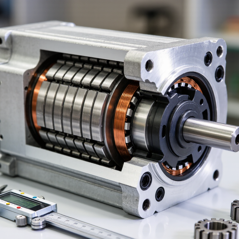
Cogging torque is the small, non-current-producing torque caused by magnetic attraction between permanent magnets and stator teeth in a BLDC motor. It appears when the rotor moves between preferred magnetic positions. You can feel it by turning an unpowered motor shaft: movement may feel stepped, rather than smooth.
This effect is strongest at low speed and zero load. It can create startup hesitation, speed ripple, audible vibration, and positioning errors. The U.S. Department of Energy’s motor-system assessments report that motor-driven equipment consumes about 70% of industrial electricity in the United States. This makes even small efficiency and motion-quality losses worth examining, especially in precision equipment. However, cogging torque is not the same as load torque or electromagnetic torque. Confusing these terms can lead to incorrect testing.
Engineers commonly reduce cogging torque by skewing stator slots, adjusting magnet pole-arc ratios, narrowing tooth tips, or optimizing the air-gap shape. Finite-element analysis helps compare these choices before prototype machining. Practical measurements still matter. A torque transducer can reveal periodic peaks that simulations miss because of material tolerances or assembly offsets. Some designs report cogging-torque reductions above 50% after optimization, but the result depends heavily on pole count, slot geometry, and magnet placement. More reduction is not always better. Skew can also lower average torque and complicate manufacturing. That trade-off deserves careful review.
| Data Dimension | Technical Description | Practical Effect | Typical Mitigation Approach |
|---|---|---|---|
| Definition | Cogging torque is the non-zero, position-dependent torque produced by the interaction between the rotor magnets and the stator teeth when the motor is not energized. | The rotor tends to move toward preferred magnetic positions, which can create detent points and uneven rotation. | Reduce the variation in magnetic reluctance around the air gap through electromagnetic and mechanical design changes. |
| Primary Cause | The stator teeth and slots create a periodically changing magnetic reluctance as the permanent-magnet rotor turns. | Torque ripple may occur even when no current is supplied to the windings. | Optimize slot and pole combinations, air-gap geometry, magnet shape, and tooth dimensions. |
| Relationship to Torque Ripple | Cogging torque is a magnetic reluctance torque component; torque ripple can also result from commutation, current distortion, saturation, and back-EMF harmonics. | Reducing cogging torque alone may not eliminate all speed or torque pulsations. | Use cogging reduction together with current control, commutation optimization, and balanced phase currents. |
| Low-Speed Behavior | Cogging torque becomes especially noticeable at low speed because electromagnetic running torque is small and position errors are more apparent. | The motor may exhibit jerky starting, uneven motion, acoustic noise, or difficulty maintaining smooth micro-positioning. | Apply sinusoidal or field-oriented current control, closed-loop position feedback, and appropriate starting current. |
| Pole and Slot Combination | The periodicity and amplitude of cogging torque depend strongly on the relationship between the number of rotor poles and stator slots. | Some combinations produce stronger or more frequent cogging harmonics than others. | Select a slot-pole combination that spreads or reduces the dominant cogging harmonics during the initial design stage. |
| Magnet Skew | Axially skewing the rotor magnets or magnetic pattern causes torque contributions from different axial positions to partially cancel. | Cogging torque and related acoustic excitation can be reduced. | Use a carefully selected skew angle, while checking its effects on average torque, back-EMF, and manufacturability. |
| Magnet Shape and Pole Arc | The magnet pole arc, edge profile, and magnetization pattern influence the air-gap flux waveform and cogging harmonics. | An unsuitable pole shape can increase torque ripple, vibration, and audible noise. | Optimize pole arc, chamfer magnet edges, or use segmented magnets to shape the air-gap flux distribution. |
| Stator Tooth and Slot Design | Tooth-tip geometry, slot opening, and local saturation affect the change in magnetic reluctance as the rotor moves. | Large or abrupt reluctance changes can increase detent torque and torque harmonics. | Use optimized tooth tips, reduced or shaped slot openings, and finite-element magnetic analysis. |
| Air-Gap Uniformity | A uniform air gap helps maintain consistent magnetic reluctance; eccentricity and dimensional variation disturb the magnetic balance. | Manufacturing errors can increase cogging, radial force variation, vibration, and bearing load. | Control rotor concentricity, shaft runout, bearing alignment, magnet placement, and stator roundness. |
| Control-Based Reduction | Cogging torque itself is position-dependent and exists without current, but commanded current can be used to compensate for its measured periodic disturbance during operation. | Closed-loop compensation can improve speed smoothness and positioning accuracy, particularly at low speed. | Map the torque disturbance by rotor position and apply feedforward compensation, with current and thermal limits respected. |
| Measurement Method | Cogging torque can be measured by rotating an unenergized motor slowly with an external torque source and recording torque versus rotor position. | The resulting waveform reveals peak-to-peak amplitude, harmonic order, and preferred rotor positions. | Use a low-speed torque test with adequate angular resolution, then compare the measured waveform with electromagnetic simulation. |
| Design Trade-Off | Methods that reduce cogging may also affect average torque, torque density, back-EMF shape, winding factor, efficiency, cost, or assembly complexity. | A design with the lowest cogging torque is not necessarily the best overall motor design. | Evaluate cogging torque together with rated torque, efficiency, thermal performance, noise, vibration, and production tolerances. |
It is the periodic magnetic resistance between rotor magnets and stator teeth. It occurs without current. The rotor may settle at preferred positions.
Disconnect the drive and rotate the shaft slowly with a calibrated torque sensor. Record torque against rotor angle through at least one full revolution. The waveform reveals resistance peaks.
Report the peak-to-peak torque and the test conditions. Include rotation speed, direction, sensor details, and motor temperature. Missing details weaken comparisons.
Bearing friction, fixture drag, poor alignment, and limited sensor resolution can distort small readings. Check the setup carefully. Small errors matter.
Different results may indicate friction or setup error. They do not always prove stronger cogging torque. Repeat the test slowly and consistently.
It can cause uneven hand rotation, rough low-speed motion, and positioning errors. Vibration and audible noise may also increase. The effect depends on the controller and mechanical assembly.
No. A bench trace does not fully represent the assembled application. Compare it with low-speed operation under real mechanical conditions. Unexpected differences deserve investigation.
Slightly skew the stator slots or rotor magnets to spread magnetic alignment. Magnet-edge shaping and tooth-width changes may also help. Geometry creates trade-offs.
Some changes may reduce average torque or increase manufacturing complexity. A simulation can guide choices, but a prototype needs testing. Plots can mislead.
Keep the winding, bearings, test speed, and measurement method consistent. Test several rotor positions before and after each geometry change. Document everything.
Cogging torque is the unwanted resistance or pulsation a BLDC motor experiences as its rotor magnets align with the stator’s teeth, even when no current is flowing. This effect comes from variations in magnetic attraction across the air gap. It can be assessed by measuring the torque required to turn an unpowered motor and may cause vibration, audible noise, uneven low-speed motion, and reduced precision.
Understanding how to minimize cogging torque in a brushless motor begins with managing the magnetic forces through thoughtful design. Options include skewing the rotor magnets or stator slots, adjusting slot and pole combinations, refining the air gap, and shaping magnetic components to distribute attraction more evenly. Each approach can affect efficiency, torque output, manufacturing complexity, and cost, so the best solution depends on the motor’s intended use. Balancing smooth operation with performance and practical production requirements helps achieve a motor that is both responsive and economical.