Sweg Motor Sweg Motor

How to Test a Brushed DC Motor With a Multimeter?

Time:2026-10-10 Author:Madeline
0%

A brushed DC motor may look simple, but its performance depends on several small electrical and mechanical parts. When the shaft stalls, sparks heavily, or refuses to turn, a multimeter can reveal useful evidence before replacement becomes necessary. Learning how to test a brushed dc motor with a multimeter helps technicians check winding continuity, terminal resistance, insulation faults, and possible brush or commutator problems.

Electrical engineer Austin Hughes describes the commutator as “a mechanical rectifier.” This short explanation matters because the commutator and brushes repeatedly transfer current into the rotating armature. A dirty commutator can create unstable readings. Worn brushes may produce intermittent contact. A healthy motor should not automatically be assumed from one normal resistance measurement.

Safety still comes first. Disconnect the motor from every power source, remove stored charge, and avoid touching rotating parts during live tests. Set the multimeter correctly, then inspect the wires, terminals, brush holders, and commutator surface. Compare resistance readings across the armature, not just between one convenient pair of terminals. Very high resistance can indicate an open winding. Near-zero resistance may suggest a short, though meter accuracy and probe resistance can confuse the result.

Small details matter.

This guide explains how to test a brushed dc motor with a multimeter through practical, repeatable checks. It also identifies common testing mistakes, including poor probe contact and misreading continuity mode. The method is useful, but it is not perfect. A multimeter cannot detect every mechanical fault, bearing issue, or fault that appears only under load. Careful observation remains part of the diagnosis.
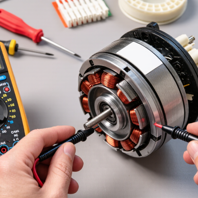
How to Test a Brushed DC Motor With a Multimeter?

Motor Basics and Multimeter Safety

How to Test a Brushed DC Motor With a Multimeter?

Motor Basics and Multimeter Safety

A brushed DC motor uses carbon brushes and a commutator to transfer current to its spinning coil. Disconnect the motor completely before testing resistance. Remove batteries, unplug supplies, and discharge nearby capacitors. Never measure resistance on an energized circuit. Set the multimeter to ohms or continuity, then touch the probes together. The display should show near-zero resistance.

Measure across the motor terminals. A small motor may show low resistance, but the exact value depends on its design. Rotate the shaft slowly while watching the display. The reading may change slightly as different commutator sections pass the brushes.

A constant open reading can suggest a broken winding, brush, or connection. Zero resistance may indicate a short. However, one reading is not proof.

Check each terminal against the metal frame. The meter should normally show very high resistance or an open circuit. Stop if the reading is unexpectedly low. That may indicate damaged insulation.

Be careful with continuity mode; a beep only confirms a conductive path. It does not prove that the motor is healthy. I avoid holding bare probes against moving parts, because slipping can cause a short circuit. Use insulated leads, dry hands, and the correct measurement range. If testing voltage during operation, use a properly rated meter and keep fingers behind the probe guards. A multimeter cannot replace a dedicated insulation tester, and that limitation matters.

Tools, Settings, and Test Preparation

Before testing a brushed DC motor, prepare a digital multimeter, insulated probes, alligator clips, and eye protection. The U.S. Department of Energy reports that motor-driven systems consume more than half of industrial electricity in the United States. Small testing mistakes can therefore create expensive diagnostic errors. Disconnect the motor completely, remove batteries, and discharge nearby capacitors. Never measure resistance on an energized circuit. Inspect the brushes, commutator, terminals, and shaft for dust, burning, or binding.

Set the meter to resistance or continuity mode first. Touch both probes together and record the lead resistance. A reading near 0.2 ohms may belong to the probes, not the winding. Measure across the motor terminals, then rotate the shaft slowly. Resistance should remain reasonably consistent. Sudden open readings suggest damaged windings or poor brush contact. Avoid current mode unless the meter is correctly placed in series. I once selected it accidentally; the fuse opened immediately. That mistake still deserves respect.

For a motor with a separate field winding, test that winding independently and compare readings with its service specification. Use DC voltage mode only after reconnecting the motor to its rated supply. The IEC 60034-1 standard emphasizes rated operating conditions and temperature limits, so a cold resistance reading cannot prove full-load health. NEMA MG 1 also stresses that motor performance depends on correct voltage and operating conditions. Document every reading, ambient temperature, and shaft position. The imperfect part is interpretation: a multimeter finds electrical clues, not mechanical wear, commutator surface quality, or load capacity.

How to Test a Brushed DC Motor With a Multimeter? - Tools, Settings, and Test Preparation

Safety note: Disconnect the motor from its power source and controller before resistance or continuity testing. Discharge connected capacitors, remove external wiring where possible, and keep fingers clear of moving parts during powered tests. Resistance values below are typical guidance for small brushed DC motors and may vary with motor size, rated voltage, winding design, temperature, and brush condition.

Test Stage Tools and Materials Multimeter Setting Test Preparation and Connection Typical Healthy Result Possible Indication
1. Identify the motor terminals Digital multimeter, insulated probes, wiring diagram if available Continuity mode or low-ohms mode Confirm which terminals belong to the motor. Disconnect switches, controllers, suppression components, and parallel loads before measuring. A clear pair of motor terminals can be identified, with no unintended connection to the frame or shaft. Unclear terminal identification can produce misleading readings or damage connected electronics.
2. Perform a visual and mechanical inspection Flashlight, small screwdriver, clean cloth, safety glasses Not applicable Inspect the brushes, commutator, terminals, insulation, bearings, ventilation openings, and shaft. Rotate the shaft by hand with power disconnected. Brushes have usable length, the commutator is reasonably smooth, the shaft turns freely, and there is no burning smell, loose hardware, or excessive play. Heavy black deposits, deep grooves, chipped brushes, binding, or excessive shaft movement may indicate mechanical or electrical damage.
3. Check winding continuity Digital multimeter with fresh batteries Lowest resistance range, or auto-ranging ohms Touch one probe to each motor terminal. If the meter has relative or zero mode, short the probes first and note the lead resistance. A stable, low resistance reading is present. Small low-voltage motors may measure from a fraction of an ohm to several ohms; the exact value depends on the motor design. Open circuit suggests a broken winding, brush, terminal, or internal connection. A reading near the lead resistance may indicate a shorted winding.
4. Compensate for test-lead resistance Digital multimeter with relative or zero function Low-ohms range Press the probe tips together firmly and record the displayed resistance. Subtract this value from the motor-terminal measurement, or use the meter’s relative function. The corrected motor resistance is repeatable when the probes are placed in the same position with similar pressure. Failure to compensate can make a healthy low-resistance motor appear to have excessive resistance.
5. Check terminal-to-frame insulation Digital multimeter, insulated probes Highest resistance range Place one probe on a motor terminal and the other on the metal frame or shaft. Repeat for the other terminal. Ensure the contact points are clean. The meter shows open circuit or a very high resistance, normally far above the winding resistance. A basic multimeter provides only a screening test. Low resistance indicates possible insulation breakdown, contamination, moisture, or contact between the winding and frame.
6. Test adjacent commutator segments Digital multimeter with fine or pointed probes Lowest resistance range Access the commutator if possible. Measure between each pair of neighboring segments while slowly rotating the armature. Adjacent segment readings are generally low and reasonably consistent. Small differences can occur because of brush position and contact quality. An open segment pair, a markedly higher reading, or a large variation may indicate a broken armature coil, loose connection, or damaged commutator.
7. Check commutator-to-shaft insulation Digital multimeter, clean probes Highest resistance range Touch one probe to a commutator segment and the other to the armature shaft or core. Repeat around the commutator. Each segment should show open circuit or very high resistance to the shaft and iron core. Continuity detected suggests an armature winding short to the shaft or core.
8. Inspect brush and commutator contact Flashlight, soft brush, contact-safe cleaning cloth Resistance or continuity mode, with power disconnected Check that the brushes move freely in their holders and that the springs apply pressure. Do not scrape the commutator with abrasive material unless the motor service instructions allow it. Brushes contact the commutator evenly, springs are intact, and the brush-to-terminal path has low, stable resistance. Intermittent readings may result from worn brushes, weak springs, contamination, or a loose brush-holder connection.
9. Verify supply voltage before a powered test Digital multimeter, suitable DC power source, insulated test leads DC voltage, range above the motor’s rated voltage Reconnect only the required motor circuit. Measure voltage at the motor terminals while the motor is connected, observing polarity and the motor’s rated voltage. The measured voltage is close to the motor’s specified operating voltage and remains reasonably stable during operation. Low voltage can cause poor starting or overheating from prolonged high current. Excessive voltage can cause overspeed, arcing, and motor damage.
10. Observe no-load current Multimeter with an appropriately rated current input, or a suitable clamp meter DC current; select the highest current range first Measure in series with the motor only if the meter and leads are rated for the expected current. Never place an ammeter directly across the power source. Current starts higher during acceleration and then decreases to a relatively steady no-load value. The exact current must be compared with the motor’s specifications. Unusually high or unstable current may indicate bearing friction, brush problems, a damaged winding, excessive load, or incorrect supply voltage.
11. Check for intermittent faults Digital multimeter, insulated probes Resistance or continuity mode With power disconnected, gently flex the motor leads and rotate the shaft slowly while monitoring the meter. Avoid shorting adjacent terminals or commutator segments. The reading remains stable, apart from normal changes when measuring different armature positions. Intermittent open readings may point to a fractured lead, poor terminal joint, worn brush, or damaged commutator connection.
12. Record and compare results Test sheet, calculator, service documentation Use the setting appropriate to each measurement Record test conditions, temperature, motor position, measured resistance, supply voltage, current, and visible defects. Compare with the manufacturer’s service data when available. Measurements are repeatable and consistent with the motor’s specifications and physical condition. Inconclusive results should be retested with clean contacts and suitable equipment; a standard multimeter cannot reliably detect every shorted turn.

Checking the Motor’s Wiring and Continuity

Before testing, disconnect the brushed DC motor from every power source. Remove batteries, controllers, and external capacitors. A multimeter set to resistance can reveal broken wiring, shorted windings, or poor brush contact.

I place the probes directly on the motor terminals, not on the connecting clips. A small, steady resistance usually indicates a continuous armature circuit. The exact value depends on motor size and design. Very low resistance may be normal in a powerful motor, but it can also suggest a winding short. An “OL” or infinite reading often points to an open wire, damaged brush, or worn commutator section. Wiggle each lead gently while watching the display. If the reading jumps, the cable may be fractured beneath its insulation.

Check each terminal against the metal motor housing. The meter should show no continuity. Any measurable connection may indicate insulation failure, contamination, or a winding touching the frame. If the motor has accessible brushes, inspect them for uneven wear, loose springs, or blackened contact surfaces. Rotate the shaft slowly by hand while measuring resistance. The reading may change slightly as the commutator segments pass the brushes. Large jumps deserve attention. I have mistaken this variation for a fault before. Clean contact surfaces can improve a test, but cleaning alone cannot repair damaged windings. Record the readings and compare them with the motor’s service specifications whenever available.

Measuring Winding Resistance and Insulation

How to Test a Brushed DC Motor With a Multimeter?

Disconnect the motor, isolate the battery, and discharge nearby capacitors before testing. The International Energy Agency reports that electric motor systems consume roughly half of global electricity, making small diagnostic errors surprisingly costly. Set the multimeter to its lowest resistance range. Touch both probes together first and record the lead resistance. Measure across the two brush terminals, then subtract that recorded value. A healthy winding usually shows low, stable resistance, often below a few ohms in compact motors. The exact value depends on wire length, temperature, and motor design.

Rotate the shaft slowly while measuring. Sudden jumps can indicate a damaged commutator segment or an intermittent connection. Do not trust one reading.

Insulation requires more care. Set the meter to its highest resistance range and test each terminal against the metal frame, with brushes lifted when practical. The display should show a stable, very high value. However, an ordinary multimeter may apply too little voltage and report “OL” without detecting weak insulation.

IEEE 43-2013 gives a commonly referenced minimum of 1 megohm plus 1 megohm per kilovolt, corrected to 40°C, but this rule is not universal for small DC motors. Use an insulation resistance tester when the service procedure permits it. Never apply test voltage to connected control electronics. IEC 60034-1 also stresses temperature effects, yet field readings are often taken cold. That is a weakness worth noting. Record winding temperature, test voltage, resistance, and time before judging the motor.

Interpreting Test Results and Finding Faults

How to Test a Brushed DC Motor With a Multimeter?

Disconnect the motor from every power source before testing. Set the multimeter to resistance mode. Touch the probes together and note the lead resistance. Subtract this value from later measurements. Measure across the motor terminals. A healthy small motor often shows low, stable resistance, but the exact value depends on its design. Do not treat a near-zero reading as proof of a short circuit. Some windings naturally measure below one ohm. An open circuit usually indicates a broken winding, brush, or internal connection. A single reading can mislead.

Rotate the shaft slowly while measuring resistance. The value should change slightly as the commutator moves between segments. Sudden jumps, repeated open readings, or large differences suggest worn brushes, dirty commutator surfaces, or damaged armature windings. Inspect the brush area if accessible. Then test the motor at its rated voltage using a suitable protected supply. If voltage reaches the terminals but the shaft does not turn, suspect mechanical binding or an internal electrical fault. If the voltage collapses, investigate the supply, wiring, or excessive motor current. Never measure current by placing the meter directly across the terminals. That mistake can damage the meter and hide the real fault. In practical testing, I have found that shaft friction is easy to overlook; a motor may pass resistance checks yet fail under load. Record cold and warm readings, because faults can appear only after heating.

How to Test a Brushed DC Motor With a Multimeter?

Measure resistance between adjacent commutator segments with the motor disconnected from its power source. Healthy readings should remain low and relatively consistent. A significantly higher reading may indicate an open armature coil, damaged brushes, or a poor commutator connection. Resistance measurements alone cannot confirm mechanical faults or insulation breakdown.

FAQS

What tools are needed to test a brushed DC motor?

Use a digital multimeter, insulated probes, alligator clips, and eye protection. Keep the work area dry. You may also need an insulation tester for deeper checks.

How should the motor be prepared before testing?

Disconnect the motor completely from its power source. Remove batteries and discharge nearby capacitors. Inspect the brushes, commutator, terminals, and shaft. Look for dust, burning, loose parts, or binding.

How do you measure winding resistance?

Set the multimeter to its lowest resistance range. Touch the probes together and record their resistance. Measure across the motor terminals, then subtract the probe resistance. Rotate the shaft slowly during measurement.

What resistance reading suggests a healthy small motor?

A healthy motor often shows low, stable resistance. Compact windings may read below a few ohms. Exact values depend on design, temperature, and wire length. Near-zero resistance does not automatically prove a short circuit.

What do sudden resistance changes indicate?

Sudden jumps or open readings may indicate damaged windings or poor brush contact. Dirty commutator segments can also cause interruptions. Worn brushes are common suspects. Do not trust one reading alone.

How can insulation be checked safely?

Test each terminal against the metal frame using a high resistance range. Lift the brushes when practical. A stable, very high reading is generally reassuring. An ordinary multimeter may miss weak insulation.

Can a resistance test prove that the motor is fully healthy?

No. Resistance testing finds electrical clues, not complete motor condition. A motor may pass cold checks but fail when warm or loaded. Mechanical friction is easy to overlook.

How should the motor be tested under power?

Reconnect it only to its rated voltage and use a protected supply. If voltage reaches the terminals but the shaft stays still, check for binding or internal faults. If voltage collapses, inspect the supply, wiring, and excessive current. Never place the meter directly across the terminals in current mode. That mistake can blow the meter fuse.

Conclusion

This guide explains how to test a brushed dc motor with a multimeter in a safe, systematic way. It begins with basic motor operation and multimeter safety, including disconnecting power, removing stored energy, and preventing accidental contact with moving parts. You will learn how to choose the correct meter mode, prepare the motor, and inspect its terminals, wires, brushes, and visible connections before taking measurements.

The testing process covers continuity checks, winding resistance measurements, and basic insulation testing to identify open circuits, short circuits, loose connections, worn brushes, or possible winding damage. The guide also explains how to interpret normal and abnormal readings by comparing results between terminals and considering the motor’s design. By combining visual inspection with careful electrical measurements, you can determine whether the motor is likely serviceable, requires cleaning or repair, or should be replaced.

Madeline

Madeline

Madeline is a dedicated marketing professional with a wealth of expertise in our company's core offerings. With a keen understanding of the industry, she brings a unique perspective to her role, consistently delivering high-quality content that highlights the superior aspects of our products. As......